Hydraulic Reactor Sizing
Determine the governing reactor area from design flow and adopted upflow-velocity limits.
Design and evaluate an Upflow Anaerobic Sludge Blanket reactor using a structured Excel workflow for automatic hydraulic sizing, reactor-module configuration, influent distribution, gas-solid separation, settler and aperture checks, treatment-performance estimation, biogas generation, sludge production, and final design review.
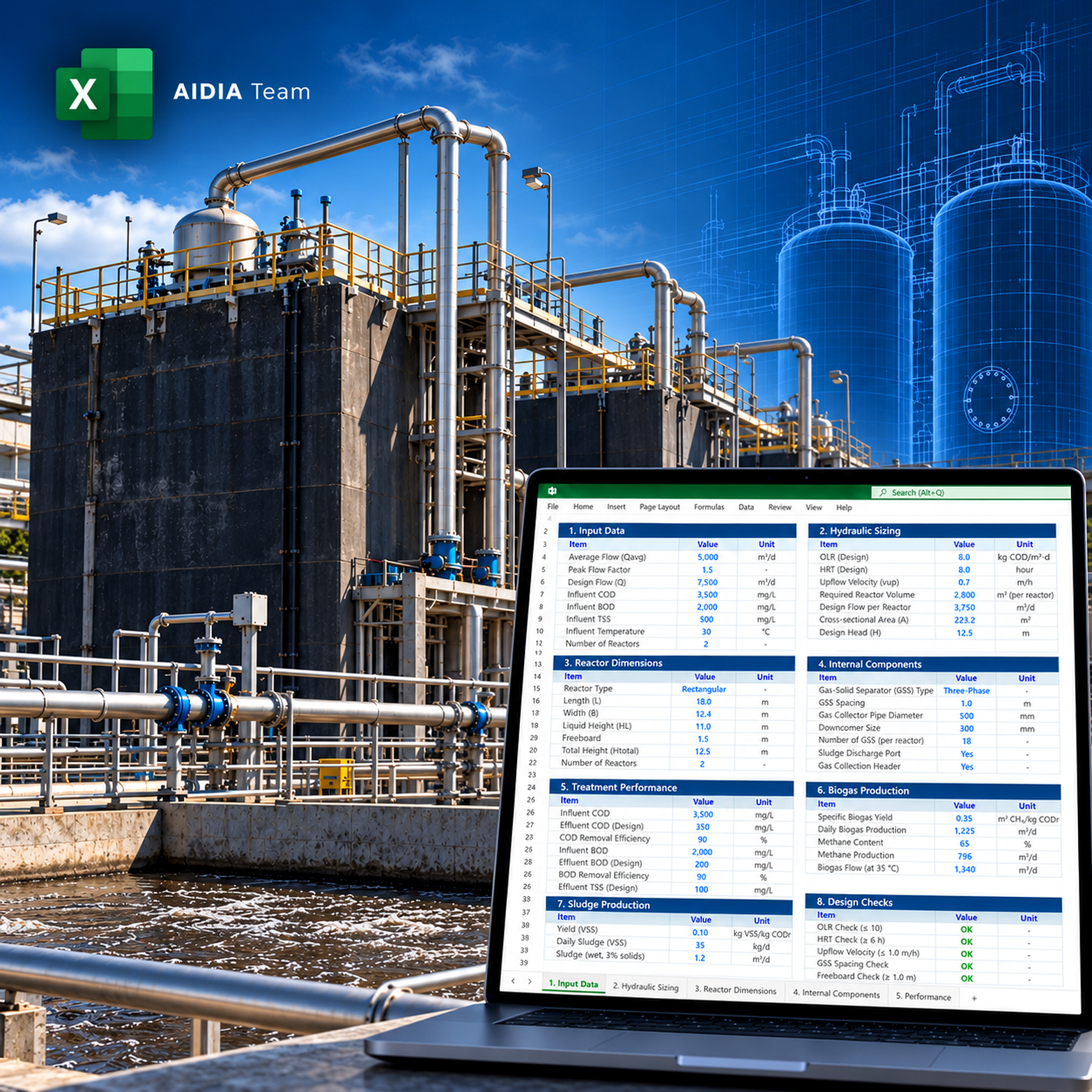
Use one connected workflow to size the reactor, establish a practical module arrangement, review the internal hydraulic components, estimate process performance, and summarize the preliminary UASB design.
Determine the governing reactor area from design flow and adopted upflow-velocity limits.
Screen reactor module counts and rounded plan dimensions until a feasible configuration is found.
Estimate distributor quantity and representative influence area at the reactor bottom.
Size gas collector / three-phase separator quantity and review biogas release rate.
Evaluate aperture velocity, equivalent opening area, effective settler area, and surface loading.
Estimate COD/BOD removal, methane and total biogas production, and excess sludge generation.
The workbook links reactor hydraulics, internal components, treatment estimates, and final design checks to the same selected geometry.
Average, maximum-hour, and optional temporary-peak influent flow.
Average, maximum, and optional peak-flow velocity checks.
Average and maximum-flow HRT linked to the final reactor geometry.
Hydraulic loading at average, maximum, and peak conditions.
Module count, width, length, useful height, and total volume.
Distributor quantity, manifold concept, and influence-area review.
Collector count, collection area, gas release rate, methane and biogas production.
Equivalent aperture count, opening width, total area, and velocity checks.
Effective settler area, compartment geometry, and surface-loading checks.
A clear path from project wastewater data to a checked preliminary reactor configuration.
Flow, COD/BOD, temperature, sludge and gas assumptions.
Target velocity, preferred height, module limits, and plan ratio.
Screen area multipliers, module counts, and rounded dimensions.
Distribution, GSS, apertures, and effective settler area.
COD/BOD removal, biogas, methane, and excess sludge.
Confirm implemented hydraulic and internal-component checks.
Actual UASB workbook screenshots. Images are sharpened for web display while preserving the original workbook content.
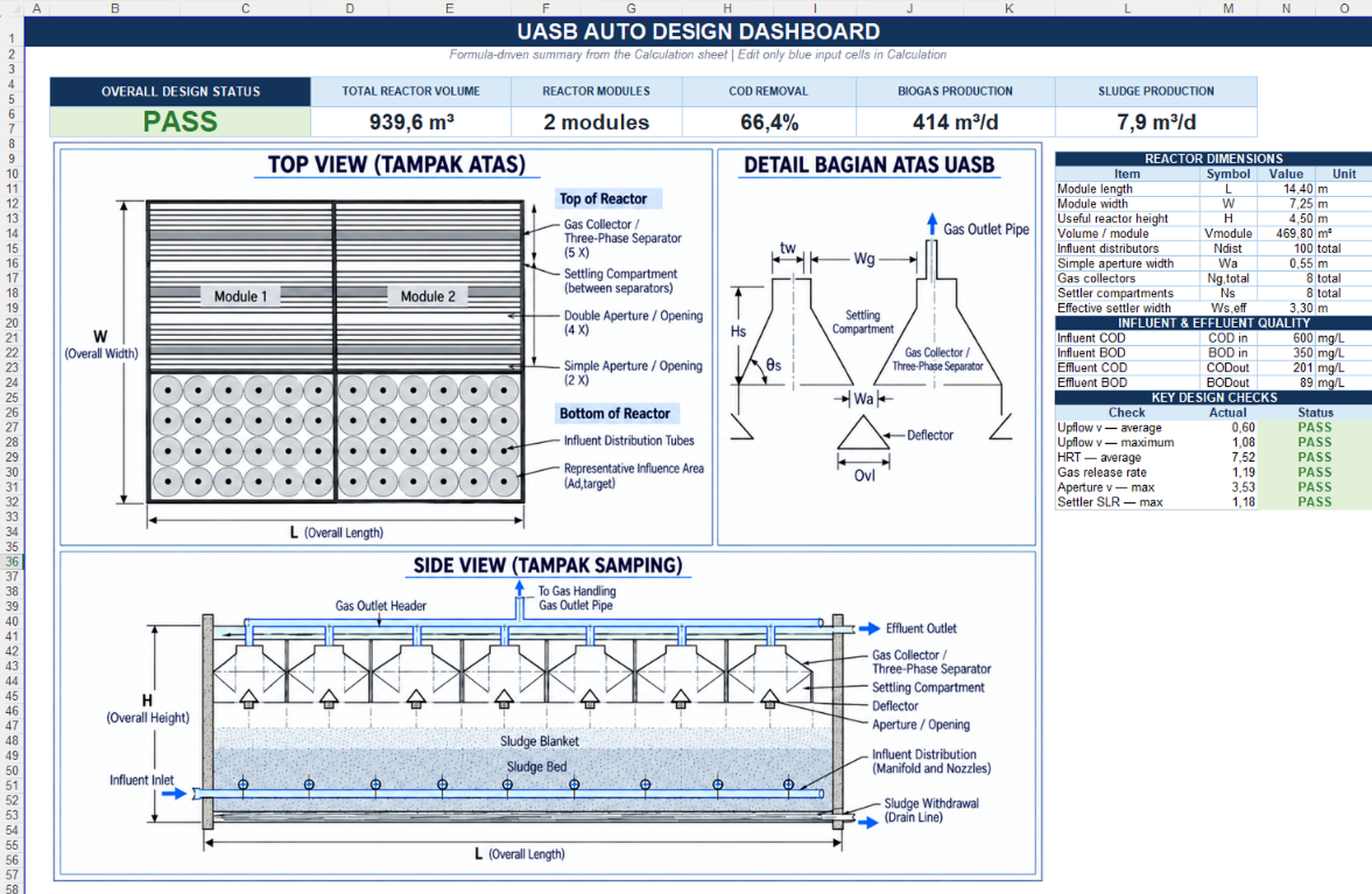
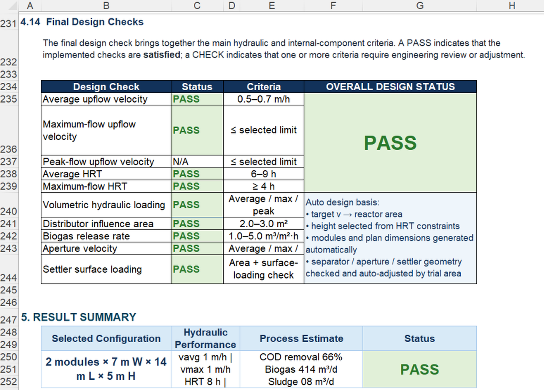
UASB design links hydraulic criteria, internal geometry, treatment estimates, and gas/sludge outputs. The workbook keeps these relationships visible in one review path.
| Design Area | Key Review Output | Engineering Purpose |
|---|---|---|
| Hydraulic sizing | Area, volume, velocity, HRT | Establish the governing reactor geometry |
| Module configuration | Module count, L × W × H | Convert hydraulic area into a practical arrangement |
| Distribution | Distributor count and influence area | Review bottom-feed distribution density |
| Gas separator / aperture | Collector count, gas release, aperture velocity | Review upper-zone hydraulic and gas-handling basis |
| Settler | Effective area and surface loading | Check preliminary solids-separation geometry |
| Process estimate | COD/BOD removal, biogas, sludge | Summarize preliminary treatment and resource outputs |
The workbook starts from design flow and hydraulic criteria, then screens module arrangements and checks the selected geometry against the implemented design basis.
Project hydraulic data establish the initial reactor-area requirement.
Required area is recalculated against the governing design-flow condition.
The selected configuration is accepted only when implemented checks are satisfied.
The workbook summarizes the implemented hydraulic and internal-component criteria as PASS / CHECK outputs.
| Check Item | Workbook Review | Why It Matters | Status Output |
|---|---|---|---|
| Average upflow velocity | Compares final area with the selected operating basis | Controls hydraulic contact and sludge-bed stability | PASS / CHECK |
| Maximum-flow velocity & HRT | Reviews the selected geometry at higher design flow | Confirms hydraulic capacity under governing flow | PASS / CHECK |
| Volumetric hydraulic loading | Checks reactor volume against design flow | Links total volume to hydraulic loading | PASS / CHECK |
| Distributor influence area | Reviews feed-point density across reactor area | Supports preliminary hydraulic distribution review | PASS / CHECK |
| Biogas release rate | Checks gas production against collector area | Supports preliminary gas-separator sizing review | PASS / CHECK |
| Aperture & settler loading | Reviews velocity and effective settling area | Checks upper-zone hydraulic separation conditions | PASS / CHECK |
A standardized AIDIA workbook structure for calculation, documentation, criteria management, and design review.
Purpose, calculation basis, engineering responsibility, references, and support information.
Project information and revision fields for engineering documentation.
Inputs, hydraulic sizing, internal components, treatment estimates, and final checks.
Top and side views, module dimensions, effluent estimate, and key design checks.
Central criteria sheet for reactor hydraulics, distribution, gas separator, aperture, and settler checks.
Engineering symbols, terminology, and units used throughout the module.
Explore other AIDIA modules that connect with wastewater-treatment design.
Bring hydraulic sizing, auto-selected geometry, internal components, treatment estimates, biogas, sludge production, and design review into one connected AIDIA Excel workflow.